Draw Involute of a Circle of 40mm Diameter
There are several guides on the web, but some of import $.25 of information seem habitually to exist missed out.
So when you lot read one of them, it might exist useful to know the following:
(for the uninitiated, at that place is more beneath – ringlet to The long answer)
- 'base circle' and 'modulus' are mysterious but important parameters. They are hands calculated.
- if you are making inch gears, you will need 'diametrical pitch' instead of modulus
- Stick to 20° pressure level angle gears unless you know why not to
- Stick to metric gears – same caveat
- For 20° gears, have more 16 teeth, or be prepared to learn a lot of advanced geometry
- Tooth length is largely contained of the pressure angle or involute. By convention:
gear teeth stick out i modulus above the pitch circle (at that place are variations).
gear teeth extend to 1 modulus below the pitch circumvolve (there are variations).
a fleck of actress clearance is dug out of the gear diameter between teeth, with a depth of 1/6 the modulus, 0.25 x diametrical pitch, or other fractions depending on who you lot mind to. - If the base circle ends up part-way upwardly the teeth, the contour of the teeth inside the base circle is a unproblematic radius
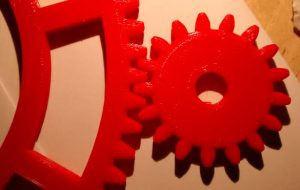 Here are two I made before (and created too in DesignSpark Mechanical)
And here are some useful resources:
- The best diy gear information source, of all the many many videos, websites and documents that I read to design my gear pair, this presentation was far clearer than the residue, and had extra information. The slides mention Shigley'due south Mechanical Engineering Design, which maybe what they are based on.
- CAD package Fusion 360 volition draw gears for you – so yous might desire to stop reading here, and download that instead.
- Too, there are ii that volition blueprint gears for you.
- Woodgears is an fantabulous on-line gear generator website which is very flexible (frankly, amazingly flexible) and has this splendid associated video.
This one handles 'undercut', which removes the gear-interference problem that prevents the easy creation of gears with fewer than 17 teeth.
The author, Matthias Wandel, volition also sell you a plan to run on your Windows computer. - Gear generator is an on-line gear generator websites by Abel that is piece of cake to use, and you lot tin can download CAD files from information technology for a small payment. Withal, it does not provide a format that DesignSpark Mechanical can directly import.
Now for some other useful gear facts if you are to diy:
- Involute is a type of shape, very important to virtually gears, and easily drawn.
- To mesh properly, anfractuous gears only need 2 things in common: modulus and pressure angle.
This does not mean that they will have the same shaped teeth. In fact, if they are different diameters, to mesh perfectly they will have different shaped teeth. - 'Pitch circumvolve' is the diameter of a pair of plain cylinders that would have the same gear ratio and centre-to-centre altitude as the intended gears.
- You can have (nigh) any gear ratio and middle-to-centre distance if you are prepared to utilize arbitrary modulus and pressure level angles, but stick to common modulus values and 20° pressure level angles if you desire your gear to mesh with a buyable gear.
Based on this last particular, hither are a bunch of things where, unless yous are really lucky, yous volition have to trade-off at to the lowest degree one to get a working gear pair:
- eye-to-middle altitude
- modulus
- force per unit area angle
- tooth count
- input-output ratio
Large alert:Whilst all of this is true to the all-time of my knowledge, everything written here is simply for gears for fiddling employ – look elsewhere to design whatsoever form of load-bearing or prophylactic-related gear.
The l-o-n-g respond..
..but it might be amend to attempt the presentation resource mentioned above.
From here on, there is a bit more than detail, missing all the stuff that you don't really need to create a xx° >16 tooth metric gear by 3D printing (cutting a gear using special tools adds more complexity).
This flake is well-nigh how to lay-out the gear tooth profile, for how many teeth to have, gyre down to 'Working out what yous need.
Involute gears
When y'all read about designing gears, you are almost always reading about 'involute' gears. Rarely will anyone demand to play with other types, such every bit hypoid gears.
Properly designed involute gears mesh nicely, operate smoothly with predictable back-lash.
As far as I can see, they add little or no velocity variation to the output shaft, and nor practice they add together much torque variation.
Everyone describing the shape of an involute – at to the lowest degree, in my experience – mentions string.
If you wind cord tightly around a cylinder, and then unwind information technology while keeping it taught, whatever signal along the unwound string describes an anfractuous as it unwinds.
The imaginary circle around which the imaginary string unwinds in gear creation is called the 'base circumvolve' , which is a special thing in gear creation.
Base of operations circle diameter = (pitch circle bore) x cos(pressure angle)
If you don't know your pitch circle diameter, read 'working out what you need' below'.
Assuming yous practice, at that place is also a prissy graphical way to piece of work out pitch circumvolve diameter, and so depict the involute.
When drawing an involute, you draw one side of 1 tooth, mirror that to make a whole tooth, and that copy that around your gear the right number of times.
A new involute has to exist drawn for each size of gear in your organisation.
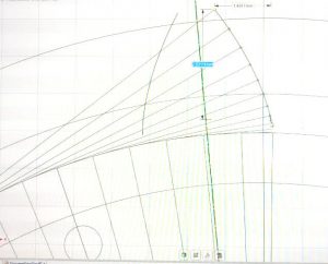
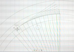 To begin drawing, lay out three concentric circles:
- One at the pitch circumvolve
- One with the bore of the pitch circle plus twice the modulus (this will exist used for the tops of the teeth)
- I with the diameter of the pitch circle minus twice the modulus, minus ane third of the modlus (this will exist used for the bottoms of the teeth)
For the crucial base circle, the circle from which the anfractuous will be 'unwound',
Distressing FOLKS, I am stopping this accident-past-accident method as other piece of work demands time – comment below if you desire it finished
Appendix: Working out what y'all need
The gear ratio and centre-to-centre altitude you want/need are the things you are probable to take an thought of.
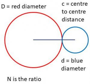 Only thinking of plain rollers that would exercise the same chore given enough friction.
N=D/d (pick your ain units)
c=D(N=1)/2
Now yous volition know the diameters of the two pitch circles
Some teeth?
Begetting in mind that only whole teeth are possible (and then no Π:1 gear ratios), it is fourth dimension to piece of work out how many teeth are needed on each gear.
They need to exist of printable size (if they are to be 3d printed).
SORRY FOLKS HERE Likewise, time pressure ways I have to stop this unless in that location is demand to finish it. Comment beneath if this is desired.
Source: https://www.electronicsweekly.com/blogs/engineer-in-wonderland/involute-gears-not-get-frustrated-designing-2020-03/
0 Response to "Draw Involute of a Circle of 40mm Diameter"
Postar um comentário